Amplifier Tutorials

1 INTRODUCTION
Radio Frequency Power Amplifiers (RFPAs) are a vital sub-system of any NMR Spectrometer or MRI scanner. Familiarity with its fundamental function, capabilities and limitations will prove beneficial to the various disciplines of technologists involved with the design, development and use of these machines. The objective is to provide an overview of amplifier technology, terminology, specifications, testing, and evaluation along with future trends in RFPA architectures.
A comprehensive definition of RF pulse parameters is initially provided as the sole purpose of the RFPA is the amplification of the RF pulse. Amplifier specifications are delineated and explained in detail with reference to their impact on the RF pulse sequences. Following the nomenclature, methods of testing and analysis are covered so one can verify performance. A section on application is provided to discuss current and future amplifier architectures, and finally a quick overview of troubleshooting is provided which relates ways in which amplifier performance anomalies can manifest in degradation of system performance.
2 KEYWORDS
Radio Frequency Power Amplifier
Transmitter
Magnetic Resonance Imaging
Nuclear Magnetic Resonance Spectroscopy
3 ABSTRACT
The Radio Frequency Power Amplifier (RFPA) can analogously be thought of as the heart of an NMR Spectrometer or MRI Scanner. Although executing a conceptually simple and fundamental task; i.e. making a small RF signal into a big RF signal, how an RFPA operationally deals with a complex RF Pulse sequence design can have direct impact on Signal to Noise Ratio (SNR) or other parameters with manifestations that are clearly visible in data or MRI scans.
An NMR Spectrometer/MRI Scanner is an extremely complex machine, an understanding of which requires knowledge of Physics, Chemistry, Analog/Digital/Radio Frequency Electronics, Digital Signal Processing etc, etc. One could spend a lifetime on any one of these disciplines relative to NMR/MRI and still fall far short of a total understanding of all there is to know. In addition, a focused expertise on a given individual discipline leaves one lacking in the others. A balanced compromise would be a sufficient working knowledge in several of the areas to gain a solid grasp on the NMR/MRI technology en masse. The objective of this chapter is to provide the NMR/MRI technologist, be they a technician, engineer, scientist, business center manager or radiologist a basic working knowledge of RFPAs such that they understand fundamentally what an RFPA does, what constitutes acceptable current state of the art RFPA performance, how to verify that performance and if it does fall short on expectations, how that shortfall may impact system performance.
4 BACKGROUND
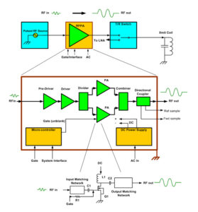
Figure 1.
A system level high level block diagram for an RFPA is shown in Figure #1. The architecture of any NMR/MRI RFPA will generally resemble this block diagram. The function of each block is as follows:
1. The Pre-Driver and Driver are low power amplifier stages that raise the power level of the small, low level input signal up from the milli-Watt range to a level high enough to drive the high power PA sections. Many Power Amplifiers may be required to achieve higher power output levels so divider/combiner networks are deployed to algebraically sum multiple amplifier output power levels together.
2. The Directional Coupler separates out precise, proportional samples of forward and reflected signal power for internal/external power monitoring and fault detection.
3. The DC power supply converts AC line voltages into DC voltages that are suitable to operate the Pre-Driver, Driver, Power Amplifiers and microcontroller.
4. The microcontroller is essentially a micro-computer that continuously runs a fixed program loop that monitors several vital operating parameters throughout the RFPA chassis; DC voltages, currents, pulse width, duty factor, RF output power, load VSWR and temperature. In the event any of these parameters get excessive to a point where damage to the RFPA is imminent, the microcontroller will put the system into a fault mode, shut off appropriate circuits and send out system status via the system interface.
5. The circuit level schematic at the bottom of Figure # 1 shows a basic amplifier stage which consists of input/output matching networks, an active device (Q1), coupling/decoupling components (C1,C2/L1, respectively), DC supply and Gating voltages. This level of circuit breakdown illustrates what is found architecturally in a pre-driver, driver or RFPA amplifier stages. Essentially only two things are done to the RF power that enters into an RFPA:? transfer and amplification. Any RF circuit in an RFPA does either one or the other function. In Figure # 1, the input/output matching networks are responsible for matching the system 50 ohm impedance with the low impedances of the RF transistors for maximum power transfer. The coupling/decoupling components (C1, C2 and L1) transfer the RF and DC energy in the appropriate directions. The transistor Q1 amplifies the RF signal.
As stated, the basic function of RFPA is simple; amplify or increase the power of an RF pulse signal applied to its input. If the RFPA was ideal, that is all it would do, the output would be an exact replica of the input waveform, and only the amplitude would be greater by some fixed multiple. But conventional RFPAs are not ideal and they will invariably distort the signal it is meant only to amplify. Just how much it can distort the signal and what is allowable is to be covered.
Since the sole purpose of the NMR/MRI RFPA is to amplify an RF pulse, its important to fully understand the parameters that define the ideal RF pulse and also define what RF pulse actually emerges from an RFPA. With that knowledge in mind; it is easier to understand how amplifier performance anomalies degrade the characteristics of the ideal pulse.
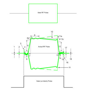
Figure 2.
Referring to the ideal pulse in Figure #2, a RF pulse train has several defining parameters, since it is ideal we assume all of them be perfect.? Propagating from the baseline on the left, we have a zero volt reference line, continuing to the rising edge of the pulse which goes from zero volts to a fixed amplitude in zero time. The pulse continues exactly at the fixed amplitude until the end of the pulse width duration and again in zero time, the amplitude drops to exactly zero volts.
If we had an ideal RFPA to amplify our ideal RF pulse, the output would look exactly as the input; only the fixed amplitude would be increased by some power amplification factor A. But ideal amplifiers do not exist and even the best ones will distort the pulse to some degree.
Observing the RF pulse it after it has exited a non-ideal RFPA. The actual RF Pulse in Figure #2 shows an amplifiers output in the Time Domain, and for illustrative and explanatory purposes, most forms of Time Domain pulse distortion that a typical NMR/MRI RFPA can induce are included. It’s interesting to note that while it takes about 4 parameters to define an ideal RF pulse; amplitude, frequency, pulse width and duty factor, it now takes over 17 parameters to characterize a pulse that has been through a non ideal amplifier. Table # 1 defines pulse parameters qualitatively.
