Amplifier Tutorials

6.0 RFPA TESTING AND EVALUATION
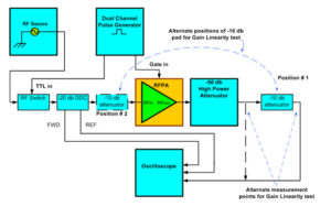
Figure 5.
The goal of this section is to provide the technologist with quick, cost effective and most of all easy way to test and evaluate an RFPAs performance. It is not intended to cover comprehensive test procedures, rather brief, discrete tests that use test equipment found in most NMR/MRI facilities and, if properly executed, can reasonably verify if an RFPA is functional within certain specification.
Figure # 5 shows only one required test equipment configuration and very few pieces of equipment needed for measurement. The other necessary test equipment is as follows (remember to be certain to use only equipment that is within its recommended calibration cycle):
A RF signal source; capable of covering the entire frequency range of the RFPA, and with at least 10 dbm (10 milli-watts) output capability of stable, clean, spurious and harmonic free sinusoidal signal.
- A dual channel pulse generator, with TTL output levels and the ability to synchronize its two pulse outputs, yet independently vary the pulse width and duty factor of each channel.
- A 4 channel, digital storage oscilloscope, with a frequency capability well in excess (at least 2 times) the maximum frequency of the RFPAs upper limit.
- A high speed RF Switch with switching speed on the order of 5 nanoseconds and one that will switch the CW RF output from the RF source producing a waveform that approaches an ideal RF pulse as closely as possible; i.e.: fast rise/fall times, zero overshoot, ringing and pulse tilt.
- A Dual, Directional Coupler (DDC) with a coupling value of -20db, directivity of better than -20 db and insertion loss less than -0.75 db across the operating bandwidth of the RFPA. Be certain to obtain exact coupling values vs. key nuclei frequencies.
- Two attenuators, one a -50db high power attenuator that can handle both the peak and average RF power output of the RFPA under test. A second, lower power -10 db power attenuator that can handle the RFPAs peak and average RF power output of the RFPA after-50 db of output signal attenuation. Be certain that both attenuators operate over the bandwidth of the RFPA under evaluation. Obtain the exact attenuation values at key nuclei frequencies either from the manufacturer using the method described using the oscilloscope.
- All required RF test cables, connectors and adapters capable of handling the peak and average RF power levels from the RFPAs output.
6.1 Useful equations and conversions
For simplicity, the tests have been designed such that only one measurement device, the digital oscilloscope (aka scope), is required. A scope only measures voltages, so for tests where it is needed to know what the power level is; conversion from volts to watts is required. Equations to do this conversion are presented along with ways to convert and work with power in dbm (power referenced to 1 milliwatt) as this will make calculations significantly easier.
A simple sine wave is shown in Figure # 4, the scope measures it in the Time Domain as a peak to peak voltage and is denoted as 2 (vp1). To convert this measured voltage to power, we first must convert the peak to peak voltage to an RMS value: vrms = (vp1) (0.707). For all the tests, the input impedance of all devices must be 50 ohms. With that in mind, the power measured of the sinusoidal waveform of Fig. # 4 Pmeasured = (vrms)2/50. Finally, as you will see shortly, if this number is converted to dbm with the following equation:, many calculations will be simplified.
With all this in mind, proceed as follows:
- Set the RF Source to the lowest operating frequency (Flow) of the RFPA
- Set Pulse generator to have a pulse width of 1 msec and 10% duty factor on the channel feeding the TTL control on the RF switch, set the channel feeding the Gate input to the RFPA to un-blank 10sec before the RF pulse is turned on and to blank 10 sec after the RF pulse is turned off.
- Using the oscilloscope, apply +10 dbm to the input of the DDC and measure the voltage at the Forward (FWD) port. Convert this to dbm and subtract from 10dbm, this is the exact coupling value (truncate coupling value beyond the tenth of a db). Repeat for the Reflected (REF) port. Enter this value in the appropriate row/column in Table # 2
- Using the oscilloscope, apply +10dbm to the input of the -50db pad and measure the voltage at the output port. Convert this to dbm and subtract from 10, this is the exact attenuation value. Repeat for the Reflected -10db pad. Enter these values in the appropriate rows/columns in Table # 2
- ?To solve for the peak to peak voltage to be measured on the oscilloscope (that is measuring voltage on the output of the 50 and 10 db attenuator) which would correspond to a full power reading, convert the full power in watts to dbm, subtract the actual, measured high power attenuators attenuation value in db from this value. Then convert the remaining number from dbm to watts, then from watts to peak to peak voltage.
For example, given a 1kW amplifier:
Pout (max) = 1kW = 60 dbm
60 dbm – 60 db (from 50 and 10 db attenuators) = 0dbm = 0.633 volts peak to peak
- Connect the equipment as shown in figure # 5, and increase the drive output of the RF source until the full output power of the amplifier is reached (i.e. the voltage from the calculation in step # 5 is seen on the oscilloscope)
- Use the scope to fully measure and characterize the pulse performance in terms of rise- time, overshoot, tilt and fall-time. Enter these values in the appropriate rows/columns in Table # 2
- Measure the peak to peak voltage at the DDC FWD and REF ports. Convert these values to dbm. Enter these values in the appropriate rows/columns in Table # 2. Remember the voltages measured by the oscilloscope are scaled down voltages whose magnitude was reduced by the DDC and output attenuator. To get the actual voltages at the terminals of the RFPA, remember to covert the voltage read by the oscilloscope to power (in dbm), then add the respective attenuation or DDC coupling values to this power to get the actual power at the input/output ports of the RFPA.
- Move -10db pad to input of the RFPA, measure the voltage at the output of the -50 db attenuator, convert to dbm and subtract from power level measured previously out of -10 db pad. Enter this value in the appropriate row/column in Table # 2
- Once all the values are entered, you can now know what the rise/fall-times, overshoot, ringing and tilt values and can calculate output power, gain, single point gain linearity (either compressive or expansive) and input Return Loss
- Repeat the process over the low, mid and high frequencies of the RFPAs bandwidth or simply at key nuclei frequencies.
Upon completing the tests and the associated calculations, the data can be compared with the published RFPAs specifications. Bear in mind that the test technique presented will yield fairly good results but may vary from the manufacturer’s data due to difference in test technique and measurement unCertainty.
